HEAT EXCHANGER WELDING TECHNOLOGY

The heat exchanger welding system is primarily designed for use in several industries including nuclear and thermal power, petrochemicals, chemicals, boilers, and air conditioning systems. It features smart, unmanned technology and incorporates advanced 3D cross laser recognition and positioning technology to precisely detect the 3D spatial locations of pipe holes. A 6-axis robot performs accurate positioning for the automatic welding of tube plates, allowing for 24/7 continuous operation. This reduces reliance on manual labor, thereby saving significant manpower resources and manufacturing costs for businesses. The products include high-precision, heavy-duty, long-arm robots, and can be customized with additional features such as external cooperative axes and quick tool change devices, enabling coordinated operations along an assembly line.

Adaptable Working Range:

  • Weld Form: Tube/Tube Plate All-Position Welding
  • Material Compatibility: Carbon Steel, Stainless Steel
  • Working Range: Up to Φ2600mm when the workpiece is stationary
  • Tube Diameter Options: Φ12mm to Φ40mm, and Φ40mm to Φ80mm (varies by selected product or customization)
  • Application Occasions: Designed for use in nuclear power plants, power stations, the chemical industry, boiler systems, heat exchangers, and the air conditioning industry.

Welding Process and Assembly Standards

  • Welding Process: All-position pulsed TIG with wire feeding.
  • Assembly Standards: Gap <0.5mm; fillet welds protrude 3-6mm, flush-end welds 0.5-1mm; surface must be oil and rust-free with beveled tube ends.
  • Welding Quality: Smooth, uniform welds free of defects, meeting all fusion and weld toe height standards.

System Workflow:

  1. Import CAD Drawings: Load workpiece CAD drawings into the system. Choose to manually select or automatically plan the robot’s initial motion trajectory using various quick planning methods (point selection, circle selection, arbitrary zoning, transverse and longitudinal skip, full automation).

  2. Establish Workpiece Coordinate System: The software automatically calculates the relative positions of the robot, the tube plate welding head, and the workpiece.

  3. Set Welding Parameters and Torch Posture: Configure or recall welding parameters like angle and radius. Use the 3D cross laser sensor to confirm the starting position of the tube hole.

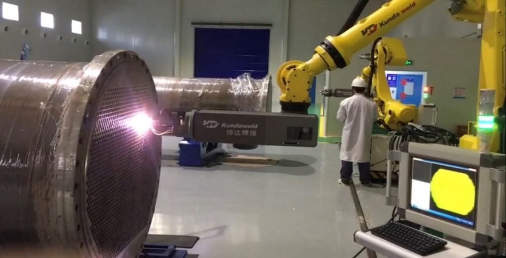
  4. Start the Welding Process: Activate the system. The 3D cross laser sensor scans the tube holes along the planned path, calculates actual deviations using software algorithms, and adjusts the robot’s motion trajectory accordingly.

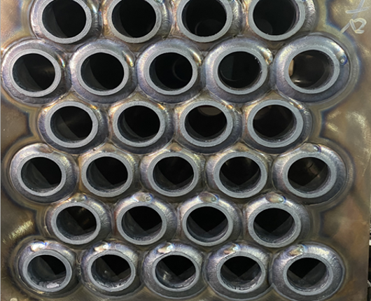
  5. Robot and Welding Torch Operation: The robot precisely positions the automatic tube plate head and starts arc welding. The welding torch uses arc voltage tracking technology to follow the weld seam trajectory in real-time, ensuring accurate tube hole welding.

  6. Repeat Process and Safety Measures: Continue the process for all welds. Upon completion, move the welding torch to a safe position and issue a sound and light alarm to indicate completion.